8 Advanced Features
This section describes several advanced features for some of the developer’s specific needs and optimizations.
8.1 Open Screen Fade of the Scenes
The SDK provides Open Screen Fade of the Scenes to be turned on through options as follows:
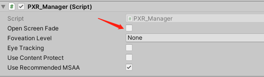
Fig 8.1 Open Screen Fade
The following figure can be used to set the Fade Time and Fade Color of the Scenes (time unit is second):
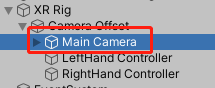
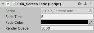
Fig 8.2 Fade Time and Fade Color after Opening the Scenes
8.2 Configure the size of EyeBuffer
The RT size is modified by modifying the value of XRSettings.eyeTextureResolutionScale. Scale (0.5-2).
Tips:
Developers are advised to use the Use Default RenderTexture, and use custom RT sizes only for special needs. For this option, developers must understand the following two points:
If the RT setting is too small, it will improve performance and reduce latency, but it will also result in lower resolution.
If the RT setting is too large, it will reduce performance and increase latency, so it is not recommended that the RT setting exceed the hardware recommended texture size. Not recommend setting more than 1.5.
8.3 Eye Tracking
Neo 3 Pro series support eye tracking feature. Eye Tracking can track the eye gaze position, optimize rendering performance with Foveated Rendering. You just need to check Eye Tracking:
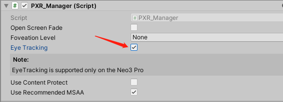
Fig 8.3 Eye tracking
8.4 Foveated Rendering
Foveated rendering can optimize the rendering of VR scenes by providing full resolution (lossless) for the center of the field of view and reducing the resolution of peripheral views (outside the focus area of eyes).
Fixed foveation rendering (FFR) means the focus of the field of view is fixed in the center of viewport, and the definition will gradually decrease from the center to peripherals. Fig 8.4 shows how to enable and configure Foveated Rendering.
Dynamic foveated rendering (DFR) refers to that the focus of the field of view follows movement of eyesight. This feature only applies to Neo 3 Pro series (supporting EyeTracking) and the configuration is as shown in 8.3 Chapter. Foveated rendering options are illustrated in the following figure:
Choose a Foveation Level other than “None” and then foveated rendering is enabled. There is no need for any extra code.
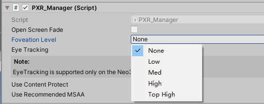
Fig 8.4 Foveated rendering
Foveation Level: Available in Low, Med, High and top high pre-defined levels. Usually it is suggested that developers choose the pre-defined level while not adjust the rendering details with self-defined parameters (unless developers bear a deep understanding of foveated rendering). Here are several parameters that affect foveated rendering:
Apart from panel settings, Chapter 7.4 can help get/set the level of foveated rendering by calling foveated rendering related API and apply/self-define parameters of it.
Foveated rendering demonstration:
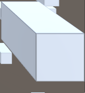
This demonstration is a screenshot of the bottom right at Low Level with 10 times zoom-in, and the image is a little blurred.
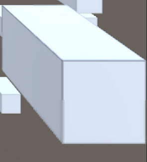
This demonstration is a screenshot of the bottom right at Med Level with 10 times zoom-in, and the image is more blurred.
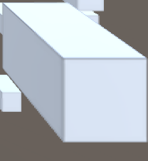
This demonstration is a screenshot of the bottom right at High Level with 10 times zoom-in, and the image is much more blurred.
8.5 Compositor Layers
In SDK rendering pipeline, contents in the scene is rendered by LeftEye/RightEye cameras, then rendered to the “eye Buffer”. After that, “eye Buffer” will be distorted and sampled by the ATW thread before it is finally rendered to the screen. However, Compositor Layers provide a rendering method that is different from “rendering scene contents directly into the eye buffer”: this method does not need to render the content to the “Eye Buffer”, but pass-through the content to ATW thread for distortion, sampling and synthesis processing, thus avoiding an extra texture sampling process and significantly improving the sharpness of the texture and video.
“Compositor Layers” are more useful for displaying messages, text, videos and textures that are intended to be the focal point of the scene. Meanwhile, it can also be used for simple environments and backgrounds. Currently, Compositor Layers support up to 15 layers (more than 15 layers will not be displayed). And in each scene there can be only 1 Equirect Layer and 1 Cylinder Layer at most. Considering the impact on performance, it is recommended that developers limit a single scene to around 4 layers.
Note:
- Using Overlay should observe that nearby objects occlude distant ones, otherwise it may cause discomfort or slight shaking.
- When using RenderTexture, Dynamic Texture option needs to be enabled. In the mean time, the width and height of the RenderTexture on LeftTexture and RightTexture must be the same, otherwise the left eye layer will not be displayed. In addition, the Tag of the Camera used to generate the image should not be set to MainCamera to avoid conflict with the same Tag of Eyebuffer’s main camera.
It is easy to use “Compositor Layers”. Just create an empty GameObject in hierarchy view of Unity Editor and then drag the PXR_OverLay.cs script (path: Runtime/Scripts/Feature/) to the GameObject.
Compositor Layer property settings related to function are as follows:
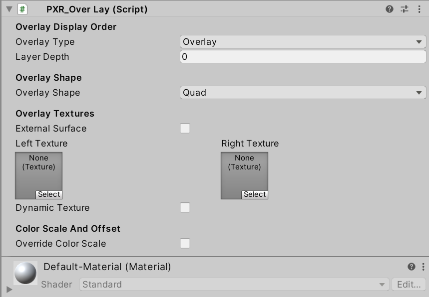
Fig 8.5 Settings
Detailed descriptions:
Overlay Type: set overlay type, and the default option is Overlay
Overlay: Texture will be displayed in front of “eye buffer”
Underlay: Texture will be displayed behind “eye buffer”
Note: Underlay relies on alpha channel of render target. When all objects are drawn behind the “eye buffer”, developers will need to hollow out an area to display the Underlay texture. A ready shader PXR_UnderlayHole (PXR_SDK/PXR_UnderlayHole) can be used. Or developers can choose to write their own shaders.Layer Index: set index value (smaller value means higher priority for composition)
[Camera](Overlay)2/1/0[EyeBuffer]0/1/2(Underlay)Overlay Shape: set overlay shape, and the default is Quad
Quad: Quadrate texture, normally used for text or messages in scene
Cylinder: Curved cylinder texture, normally used for curved UI
Note 1: Center of Transform component will be the center of the cylinder. Transform.scale will be used as the size of cylinder, [size.z] as the radius of cylinder, [size, y] as the height of cylinder, and [scale.z] as the arc length of cylinder.
Note 2: When using Cylinder texture, camera needs to be placed inside inscribed sphere of the cylinder. Overlay won’t be displayed if camera is too close to the inscribed sphere surface.
Equirect: Sphere texture, normally used for 360/180 video players (not available for Underlay currently)
External Surfaces: Checking this option indicates the layer will obtain texture from Android Surface externally. (e.g. texture of Android Player)
Note: When enabled, an Android Surface will be initialized and managed by SDK, meanwhile it will be rendered directly to Compositor Layer (We suggest enable ExternalSurface to gain sharper video images, i.e. using Android player plugin to send video texture to Compositor Layer for compositing).Texture: Assign textures for left and right eye
Left Texture: Texture to be displayed on left eye.
Right Texture: Texture to be displayed on right eye.
Dynamic Texture: Set Textures as dynamic texture, refreshed every frame.
Override Color Scale: Set the color scale and color offset of the layer
Color Scale: the zoom scale of the color value of the layer
Color Offset: the offset of the color value of the layer
Overlay & Underlay
If developers apply the feature to their project, follow these steps:
- Create a Quad in the scene, name it OverlayTransform, then adjust its position so that it is in the visible position of the Camera. After determining the display position, uncheck the Mesh Render and Mesh Collider components on the Inspector view panel and add PXR_OverLay script.
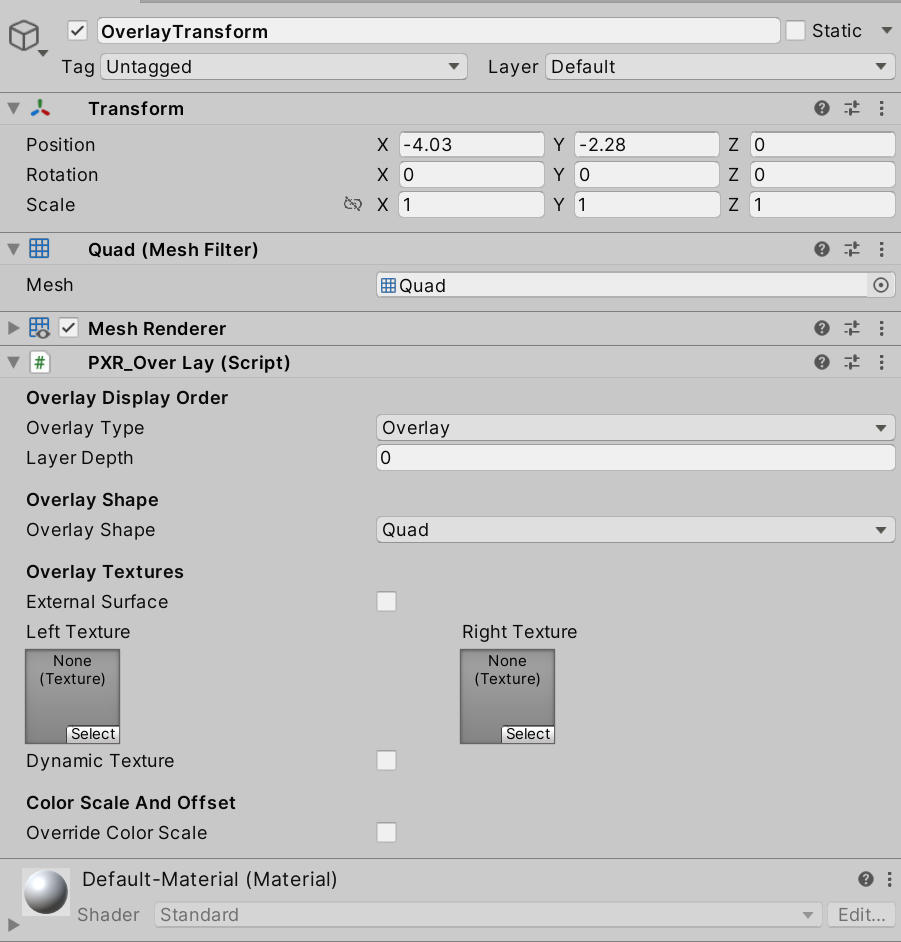
Fig 8.6 Add PXR_Overlay script
Tips: The Transmit Layer will use the Quad’s Transform information: position, rotation, scale.
Overlay Type: Set overlay layer type as Overlay;
Layer Index: Set index value (smaller value means higher priority for rendering);
Overlay Shape: Select the overlay shape as Quad;
Textures: Specify the 2D texture to be passed through (Tips: the left and right eyes should specify the same texture, otherwise it will cause dizziness as the content of the left and right eyes are different);
Color Scale And Offset: Adjust the parameters of chromatic aberration and color shift in the pass-through layer
Tips: Developers who need to dynamically modify passthrough 2D textures can call the SetTexture(Texture texture, bool dynamic) interface in the PXR_OverLay.cs script. Parameters: texture: passthrough 2D texture to be modified; dynamic: whether it is a dynamic texture.
- Package and install to the device to experience the effect.
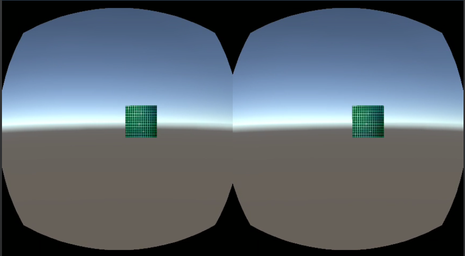
Fig 8.7 Operation effect
360 panorama texture
Normally it takes three steps to achieve “360 panoramic view”:
1.Create a sphere model in the scene;
2.Create a “360 panorama texture”, assign it to the sphere model and modify the shader to remove the front rendering (Cull Front);
3.Place the Camera in the center of the sphere;
The pass-through layer takes only two steps:
1.Create an empty object in the scene and bind the PXR_OverLay.cs script;
2.Set the Overlay shape as Equirect type and specify a “360 panorama texture”
If developers apply the feature to their project, follow these steps:
1.Same as in the “2DOverlay & 2DUnderlay”
2.Set property parameters on the script inspector;
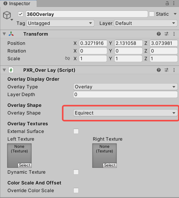
Fig 8.8 Set property parameters
Overlay Type: Set overlay layer type as Overlay;
Layer Index: Set index value (Smaller value means higher priority for composition);
Overlay Shape: Set overlay shape as Equirect;
Textures: Specify the same 360 panorama texture for the left and right eyes;
- Package and install on the device to experience the effect.
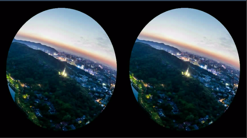
Fig 8.9 Operation effect
Head-Locked & World-Locked Mode
By default, the “pass-throuigh layer” is in World-Locked mode. To implement Head-Locked mode, you only need to create an empty Transform under the MainCamera node and bind the PXR_OverLay.cs script.
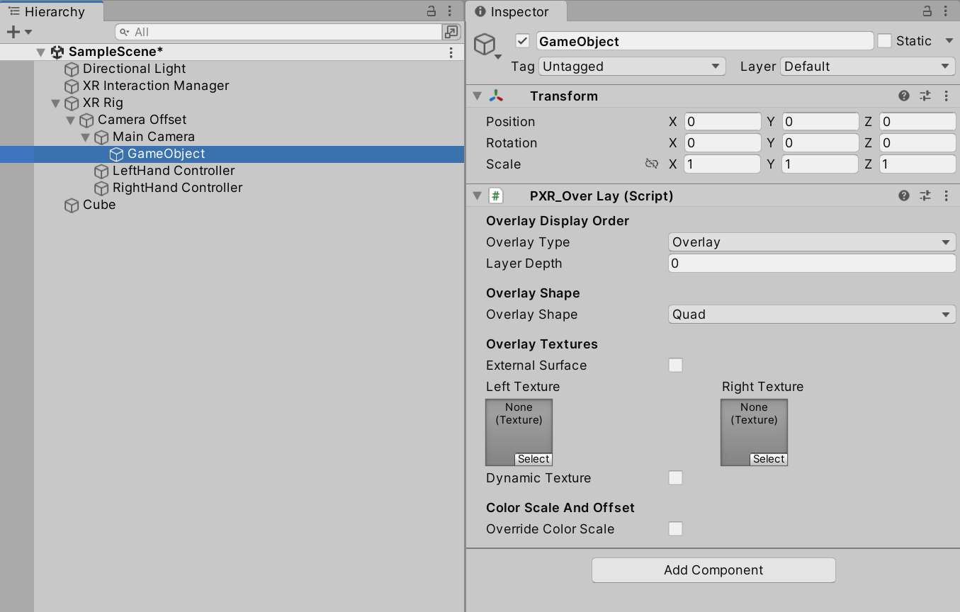
Fig 8.10 Head-Locked mode
8.6 Tracking Origin
SDK allows setting the Tracking Origin. The default value is Floor. When set as Floor, tracking origin will be calculated by the height above the ground detected by headset. (Only applicable on devices supporting ground detection like Neo 2). When set as Device, which is also known as Eye level, the application won’t calculate tracking origin according to the height detected by the device. Device is recommended for sitting usage while Floor is better for standing usage. However, it is subject to the actual situation.
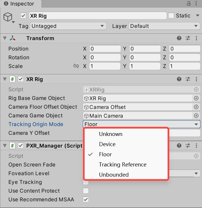
Fig 8.11 Tracking Origin options
Tips: Camera Y Offset is the offset added along with Y direction of Camera when Device is selected. This offset value is ineffective when Device is selected.
8.7 Multiview
Multiview is based on native Unity multiview feature. It uses one camera to fulfill stereo rendering, reducing half of Draw Call and Occlusion Culling. Using this feature can increase frame rate dramatically in complex scenes. But multiview don’t support post processing.
Related instructions:Single Pass Stereo rendering / Unity - Manual: XR SDK Display subsystem
Multiview shown below is the original single pass mode:
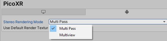
Fig 8.12 Enable Multiview
8.8 Application copyright protection
Developers are allowed to use this function during development and debugging phases as well as final release to the Pico Store.
Entry: go to Menu/PXR_SDK/ Platform Settings, and enable “User Entitlement Check”.
8.8.1 Entitlement check simulation during development and debugging phases
In the development stage, developers can simulate the user entitlement check process by filling in the development device SN code in the configuration interface.
In the menu, click PXR_SDK/ Platform Settings to open up Platform Settings as shown in the figure below:
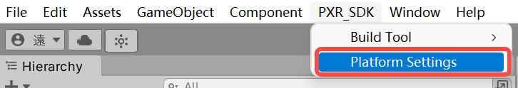
Fig 8.13 Platform Settings Option
Entitlement Check Simulation is disabled by default. After checking this option, developers can input the number of allowed devices and corresponding SN codes. Editor mode provides entitlement check validation function to simulate and test user entitlement.
Steps to get SN code of the device:
- Enter Settings – About – Serial Number
- Use adb command “adb devices” to get device SN code
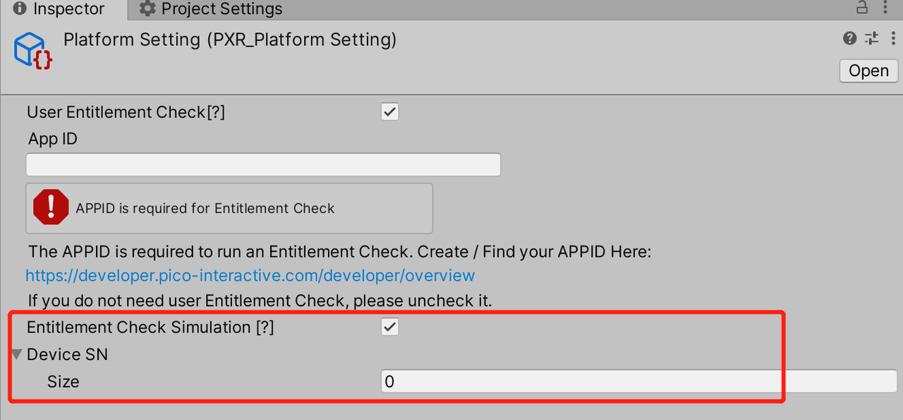
Fig 8.14 Platform Settings Inspector
8.8.2 Copyright protection after official release
The figure below shows that after User Entitlement Check is checked, inputting the correct App ID can enable this function. The App ID is the unique ID assigned to an app by the Pico Developer Platform. Developers can apply for App ID at https://developer.pico-interactive.com/developer/overview.
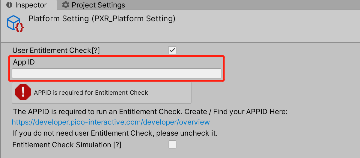
Fig 8.15 App ID inputting
| ReturnValue | Meaning |
|---|---|
| 0 | Success. |
| -2 | Service does not exist. |
| -3 | Service binding failed. |
| -4 | Catching exception code. |
| -5 | Timeout. |
| 10 | The package name is missing. |
| 11 | The APPID is missing. |
| 13 | The package name and APPID do not match. |
| 20 | The user has not logged in. |
| 21 | The user has not purchased. |
| 31 | The application was not found. |
| 32 | The purchasing SN does not match with the device SN . |
Notes: Development devices with SN code filled in entitlement check simulation will pass the content copyright protection check by default after the app is uploaded to the Pico Store, and no formal copyright protection check will be carried out. If developers need to carry out formal copyright protection check on the development device after the app is on the Pico Store, please close the “Entitlement Check Simulation” when compiling the formal version.
8.9 PassThrough
SDK provides method to acquire camera passthrough images (not support Vulkan currently). The method to open it is as follow:
- Attach script PXR_PassThrough.cs to desired object
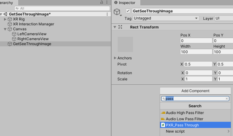
Figure 8.16 Attach PXR_PassThrough.cs script
- Create Raw Image to receive left-eye and right-eye camera view
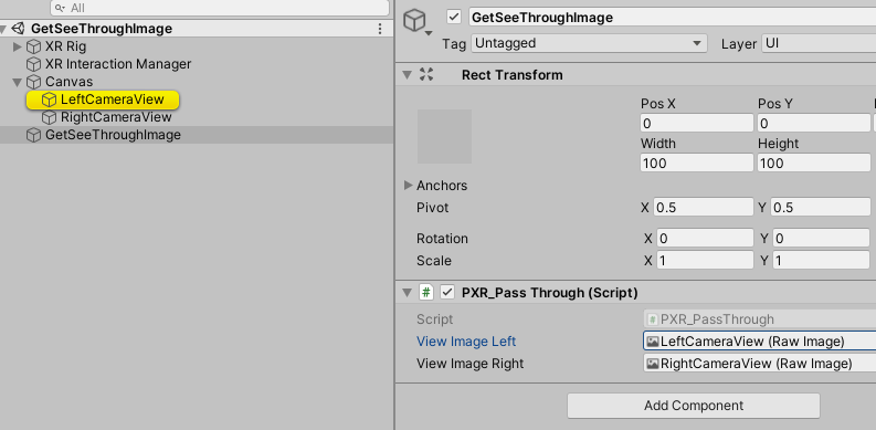
Figure 8.17 Create Raw Image for camera images
- Package and build. Click CONFIRM button to acquire camera images.
8.10 Anti-Aliasing
The SDK provides recommended Multi-Sample Anti-Aliasing setting, enabled by selecting the Use Recommended MSAA option. Currently, the recommended MSAA value is 4. The method to enable the option is shown in the figure. Uncheck the option to customize MSAA yourself.
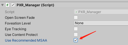
Figure 8.18 Use Recommended MSAA
8.11 Quick compilation tool
The tool leverages gradle cache to speed up the build process. It only updates the increment of compilation during the compilation process by using gradle cache, thus reducing the time for compilation and deployment by 10% to 50% compared to that of the Unity’s compilation file, and the final.apk file is exactly the same as the Unity’s compilation file. However, to release the final.apk, you must use Unity’s compilation function.
To use this function, please follow these steps:
1.Open Build Settings and select scenes that you want to package
2.Click Pvr_UnitySDK->Build Tool->Build And Run in the menu bar
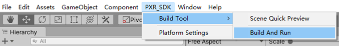
Figure 8.19 Quick compilation
Note: Currently, this feature is only available in the Unity editor for Windows.
8.12 Scene Quick Preview Tool
This tool decompose project into multiple asset bundles and upload to Pico devices. When developer made changes to the project, using this tool will update only essential changes to Pico devices when building new version.
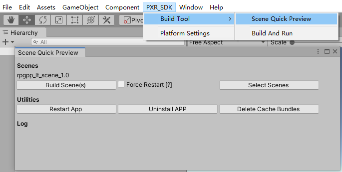
Figure 8.20 Scene Quick Preview
To use Scene Quick Preview, please follow the steps below:
To use Scene Quick View, please follow steps:
- From Menu Bar select PXR_SDK -> Build Tool -> Scene Quick View to open Quick View Panel.
- Click “Select Scenes” button and choose the scenes for Quick View Tool to build.
- Click “Build Scenes(s)” button and start compiling.
Additionally, you may also use following
“Force Restart[?]”: When this option is enabled, the application restarts on each re-compiling.
“Restart APP”: Restart the application.
“Uninstall APP”: Uninstall the application.
“Delete Cache Bundles”: Delete cache files generated during compilation
Note: Currently, this feature is only available in the Unity editor for Windows.
8.13 Configure the refresh rates of screen
The SDK provides the function of configuring the refresh rates of screen, which is configured by setting the related options of Display Refresh Rates as follows:
1. Default:System default.
2. RefreshRate72:The maximum refresh rate is 72hz.
3. RefreshRate90:The maximum refresh rate is 90hz.
- RefreshRate120:The maximum refresh rate is 120hz.
Note: RefreshRate120 feature requires the device system software version to be c000_rf01_bv1.0.1_sv2.29_20220121_b384 and above.
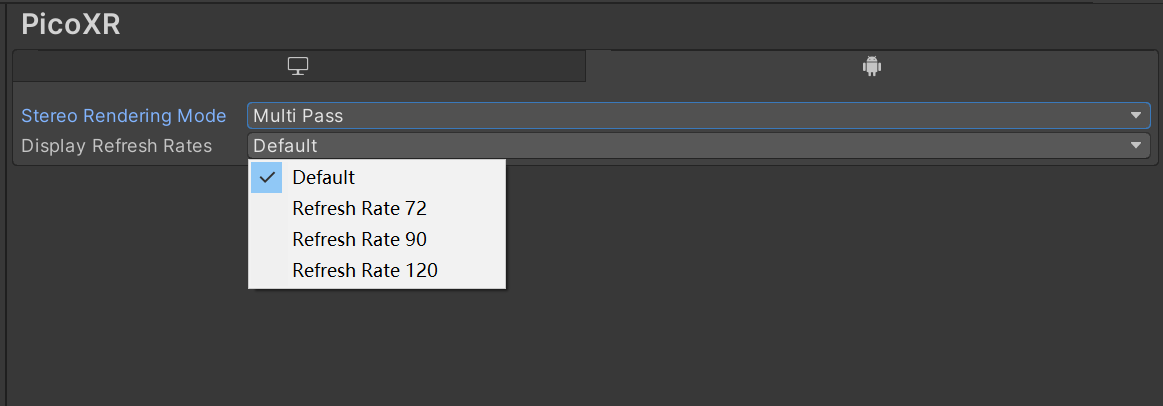
Figure 8.21 Screen refresh rate settings
8.14 Mixed Reality Capture
Mixed Reality Capture (MRC) allows you to record and share virtual reality content. Bringing real people directly into virtual scenes and replacing avatars seamlessly displays the virtual world interacting with real people.
How to use MRC in SDK:
- Updated the SDK version to v2.0.3 and above.
- Create an empty gameobject in the initial scene (make sure it has no parent object) and add the PXR_MRC script.
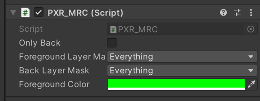
Figure 8.22 PXR_MRC script
OnlyBack:The default value is false. When set to true the MRC will only record the rear view.
ForfroundLayerMask:Select the layer for foreground camera recording.
BackLayerMask:Select the layer for rear view camera recording.
ForegroundColor:The background color of the foreground camera. It is not supported to be modified at the moment.
- Install Runtime and the new application. Open the application once first to see if it starts properly.
- Prepare an Apple 12 or above mobile phone and 5G wifi, the phone and the headset need to be under the same WIFI.
- Installing calibration applications in the HMD.
- Install the MRC beta mobile assistant on your mobile phone. The user account should be the same in HMD and mobile phone.
- Follow the prompts of Mobile Assistant for MRC video recording.
Note:If Vulkan is used in the project, please select the color space to Gamma instead of Linear.