5 Hardware product development guide
This chapter will introduce the use method of SDK on Pico hardware products.
5.1 Pico Neo 3 Controller Usage
1、Add two MotionController components to the default Pawn class in the game, named MotionController_Left and MotionController_Right respectively. Set them at the same level as Camera component.
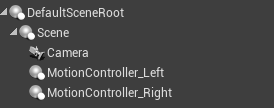
Figure 5.1 Add MotionController component
2、Select MotionController_Left. Locate the Hand property under its detail panel, and modify it to Left. The component will move following the main controller.
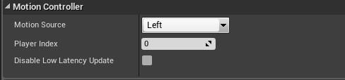
Figure 5.2 Hand property setting
3、Using the same steps, set the Hand property of MotionController_Right to Right.
4、Add a model to MotionController: :
Approach A: In the MotionController detail panel, add the model under the Visualization sub-item. The display can also be achieved by selecting “Show Plugin Content.”
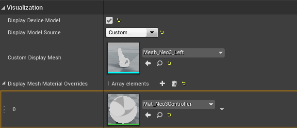
Figure 5.3 Add the controller model
Approach B: Add component Static Mesh, and set its parent component as the Motion Controller component. Then set the Mesh of the Static Mesh component as the corresponding model.
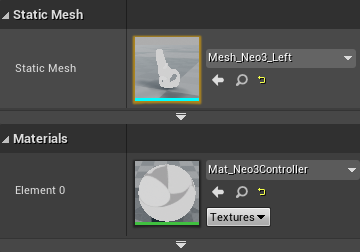
Figure 5.4 Add Pico Neo3 controller model
It should be noted that Pico SDK package the controller with key animation into an Actor, to reuse it, please attach it to the Pawn or Character in your level.
5.2 Pico Neo 3 Input instructions
- Key event instructions
The corresponding events driven by blueprint nodes for keys used by Neo 2 and Neo 3 controller are as follows:
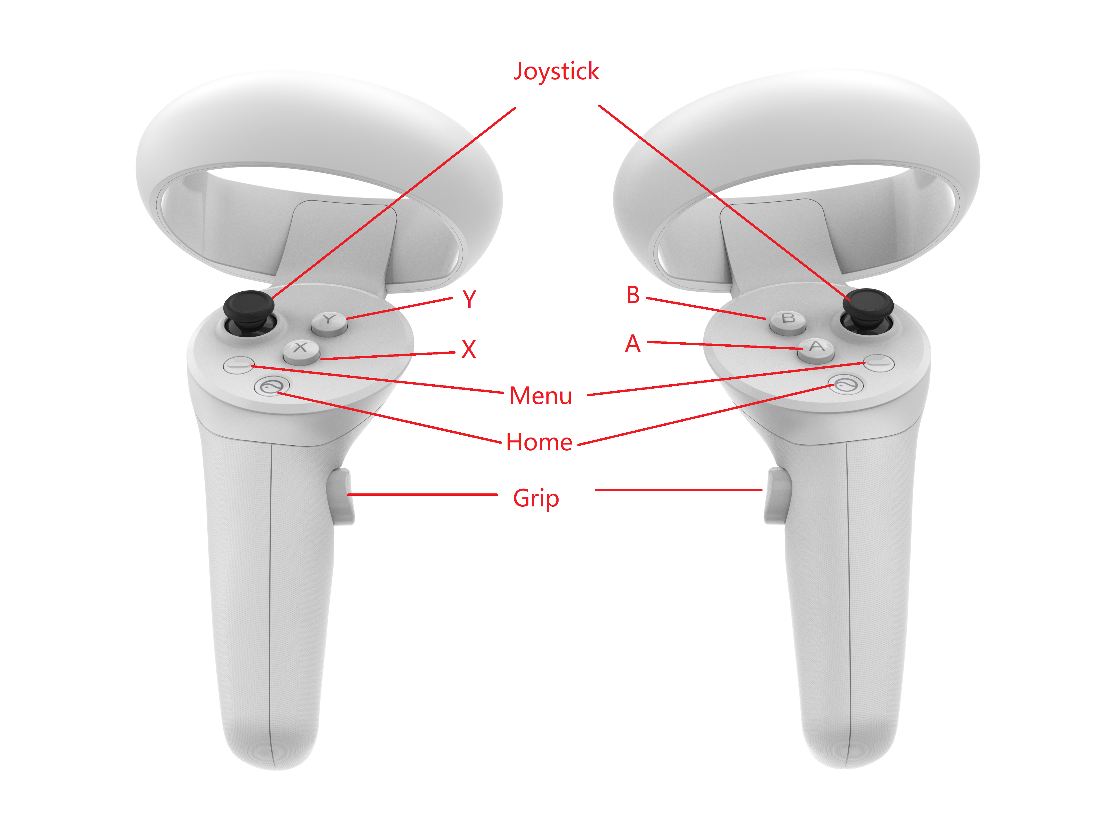
Figure 5.5 Key mapping (front view)
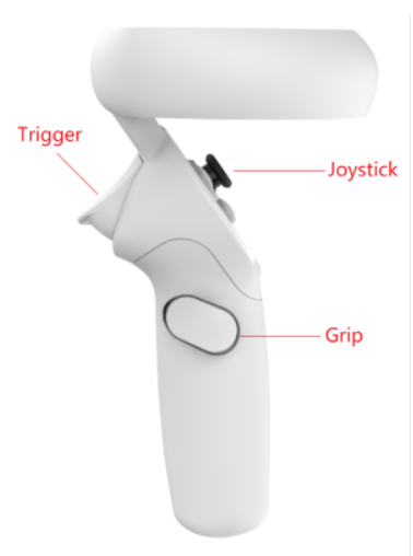
Figure 5.6 Key mapping (side view)
| Key | Event | |
| Home | Left | 
|
| Right | 
|
|
| Menu | Left | 
|
| Right | 
|
|
| Trigger | Left | 
|
| Right | 
|
|
| Grip | Left | 
|
| Right | 
|
|
| X/A | Left | 
|
| Right | 
|
|
| Y/B | Left | 
|
| Right | 
|
|
| Joystick | Left | 
|
| Right | 
|
- Axis
The axis input of the Pico Neo 3 controller:
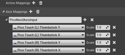
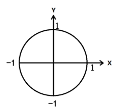
Figure 5.7 Schematic diagram of Pico Neo 3 controller touchpad
5.3 Pico all-in-one key
The following table refers to the correspondence between the keys on the all-in-one machine and the key values in UE.
| HMD Key | UE Input Key |
|---|---|
| Confirm Key | 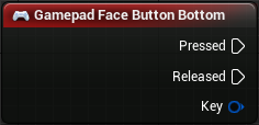
|
| Home Key | Android standard HOME (occupied by the system) |
| Volume Up Key | 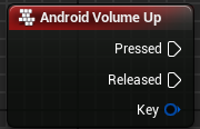
|
| Volume Down Key | 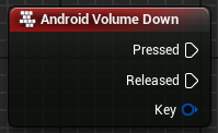
|
| Return key | 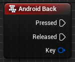
|