This chapter will introduce the use method of SDK on Pico hardware products.
5.1 Pico G2/G2 4K
5.1.1 User manual
Please follow these steps to use Pico G2 controllers:
- Add the MotionController component to the default Pawn class in the game to make it have the same level as the Camera component:
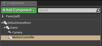
Figure 5.1 MotionController component addition
This component is not affected by the Hand property, for example, if the left and right hands need to be changed, please go to the system setup to modify it:
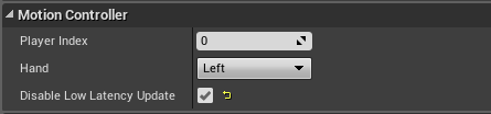
Figure 5.2 Disable Low Latency Update checking
Once packaged and installed, the component will will follow the position/orientation of the Pico controller.
- Add a model to MotionController:
Please add the model under the Visualization sub-item of MotionController detail panel (the display can be achieved after checking “Show Plugin Content”):
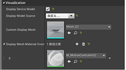
Figure 5.3 Add Pico controller model
It should be noted that in our plug-in directory, we package the controller with key animation into an Actor, and if you want to reuse it, please attach it to the Pawn or Character in your level.
5.2 Pico Neo 2 / Neo 3
5.2.1 User manual
- Add two MotionController components to the default Pawn class in the game (named as MotionController_Left and MotionController_Right respectively), and make them have the same level as the Camera component:
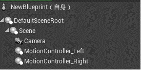
Figure 5.6 Add MotionController component
- Select MotionController_Left. Find the Hand property under its detail panel and modify it into Left. Thus the component will move following the main controller:
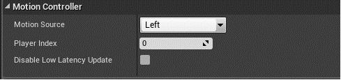
Figure 5.7 Hand property setting
- Similarly the Hand property of MotionController_Right should be set as Right.
- Add a model to MotionController: please add the model under the Visualization sub-item of MotionController detail panel (the display can also be achieved after checking “Show Plugin Content”):
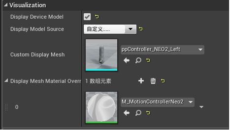
Figure 5.8 Add the controller model
It should be noted that Pico SDK package the controller with key animation into an Actor, to reuse it, please attach it to the Pawn or Character in your level.
5.2.4 Related blueprint nodes
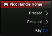
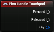
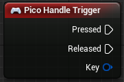
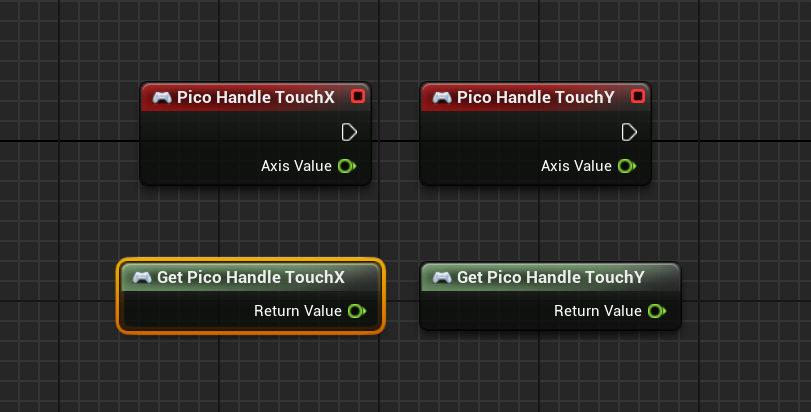
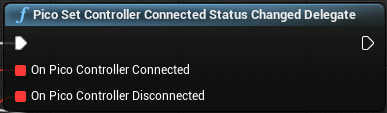
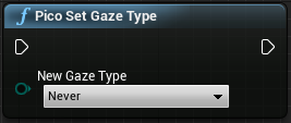
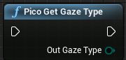
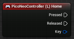
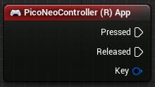
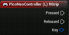
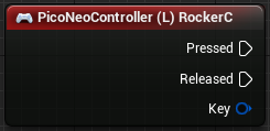
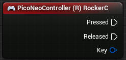
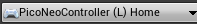
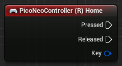
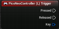
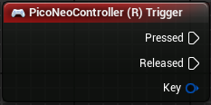
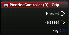
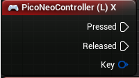
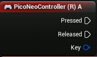
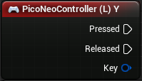
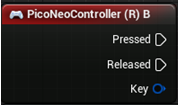
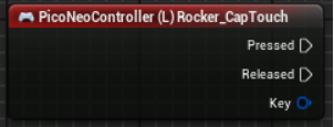
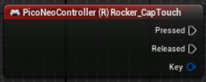
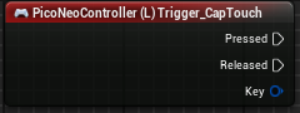
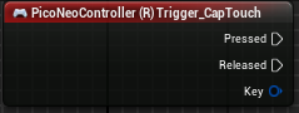
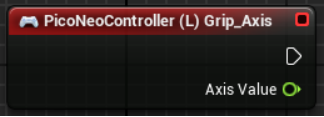
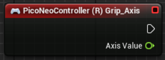
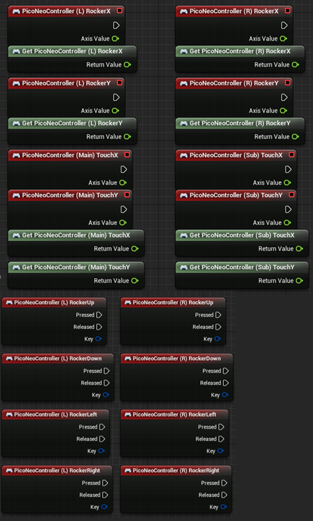
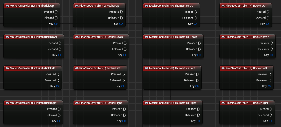
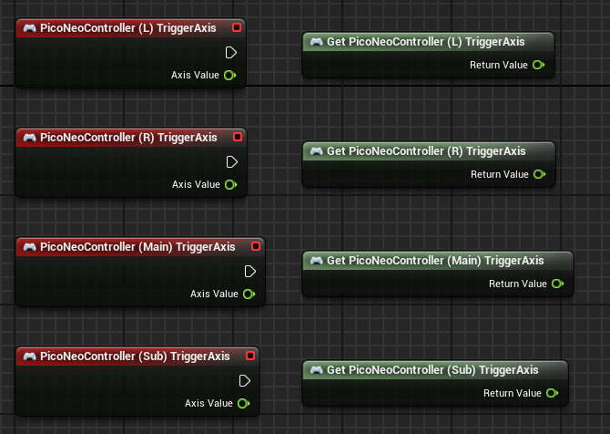
For the Pico Neo controller, we provide several APIs in the form of blueprint nodes. Right click on the event graph and expanding Pico Neo->Controller, and these APIs can be seen:
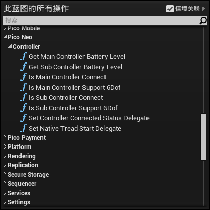
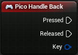
Figure 5.16 API of Pico Neo controller
The detailed use methods of these APIs are as follows:
|
Function |
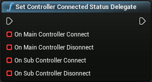
Set the customized controller disconnection and reconnection events |
| Input |
On Main Controller Connect: Main controller reconnection
On Main Controller Disconnect: Main controller disconnection
On Sub Controller Connect: Sub controller reconnection
On Sub Controller Disconnect: Sub controller disconnection |
| Output |
None |
| Return value |
None |
|
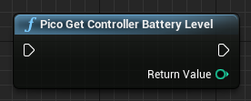
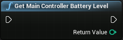
Function |
Get the battery level of the main controller |
| Input |
None |
| Output |
None |
| Return value |
The battery level of the main controller, 1-5 |
|
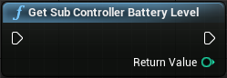
Function |
Get the battery level of the sub controller |
| Input |
None |
| Output |
None |
| Return value |
The battery level of the sub controller, 1-5 |
|
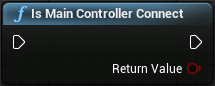
Function |
Determine if the main controller is connected |
| Input |
None |
| Output |
None |
| Return value |
True-connected, false-not connected |
|
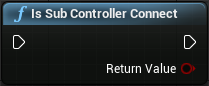
Function |
Determine if the sub controller is connected |
| Input |
None |
| Output |
None |
| Return value |
True-connected, false-not connected |
|
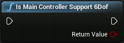
Function |
Determine if the main controller supports 6DoF tracking |
| Input |
None |
| Output |
None |
| Return value |
True-support, false-not support (i.e. 3DoF tracking) |
|
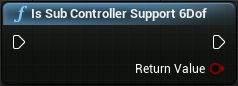
Function |
Determine if the sub controller supports 6DoF tracking |
| Input |
None |
| Output |
None |
| Return value |
True-support, false-not support (i.e. 3DoF tracking) |
|
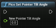
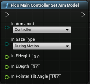
Function |
Set MainController arm model |
| Input |
Arm model related parameters |
| Output |
None |
| Return value |
None |
|
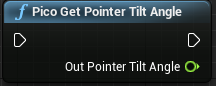
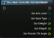
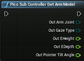
Function |
Get MainController arm model |
| Input |
None |
| Output |
Arm model related parameters |
| Return value |
None |
|
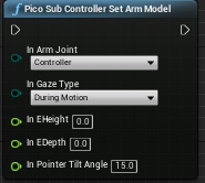
Function |
Set SubController arm model |
| Input |
Arm model related parameters |
| Output |
None |
| Return value |
None |
|
Function |
Get SubController arm model |
| Input |
None |
| Output |
Arm model related parameters |
| Return value |
None |
|
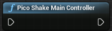
Function |
Shake Main Controller (the left controller of Neo 2) |
| Input |
None |
| Output |
None |
| Return value |
None |
|
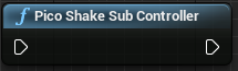
Function |
Shake Sub Controller (the left controller of Neo 2) |
| Input |
None |
| Output |
None |
| Return value |
None |
|
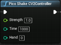
Function |
Shake Neo 2 Controller (Also applicable for Neo 3) |
| Input |
Strength - The shaking strength, ranging from 0 to 1
Time - The shaking time, ranging from 0 to 65535 ms
Hand - 0 for the left controller, and 1 for the right controller |
| Output |
None |
| Return value |
None |
|
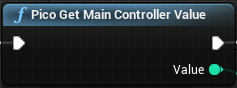
Function |
Get main controller value |
| Input |
None |
| Output |
0 - Left 1 - Right |
| Return value |
None |
|
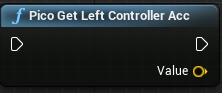
Function |
Get the linear acceleration of Neo 2 left controller or Neo main controller |
| Input |
None |
| Output |
Linear acceleration with mm/s^2 as the unit |
| Return value |
None |
|
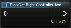
Function |
Get the linear acceleration of Neo 2 right controller or Neo sub controller |
| Input |
None |
| Output |
Linear acceleration with mm/s^2 as the unit |
| Return value |
None |
|
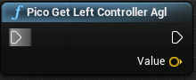
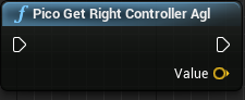
Function |
Get the angular velocity of Neo 2 left controller or Neo main controller |
| Input |
None |
| Output |
Angular velocity with rad/s as the unit |
| Return value |
None |
|
Function |
Get the angular velocity of Neo 2 right controller or Neo sub controller |
| Input |
None |
| Output |
Angular velocity with rad/s as the unit |
| Return value |
None |
|
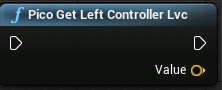
Function |
Get the linear velocity of Neo 2 left controller |
| Input |
None |
| Output |
Linear velocity with mm/s as the unit |
| Return value |
None |
|
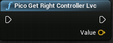
Function |
Get the linear velocity of Neo 2 right controller |
| Input |
None |
| Output |
Linear velocity with mm/s as the unit |
| Return value |
None |
5.2.5 Security boundary
Please refer to Chapter 6.2 to see the open interfaces.
5.2.6 Disable position tracking function
To develop 3Dof applications, disable the position tracking function.
Open the menu Edit->Project Settings…, find the Plugins sub-item, and check the following two options as needed:
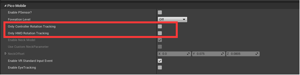
Figure 5.17 Pico Neo/Neo 2 6DoF options
5.2.7 Adjusting controller model angle
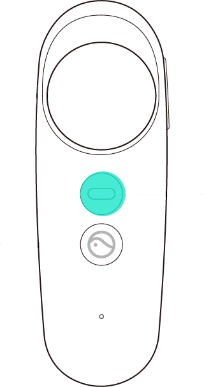
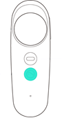
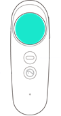
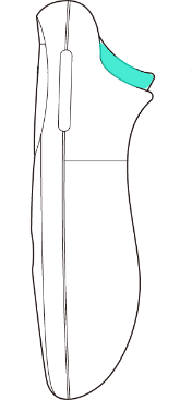
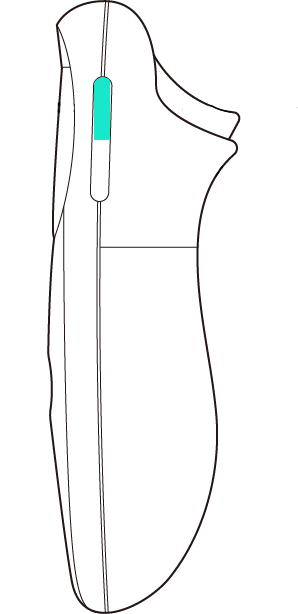
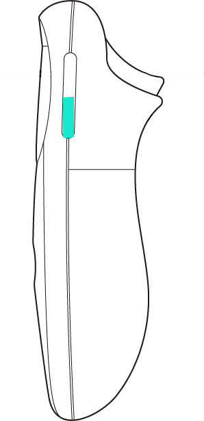
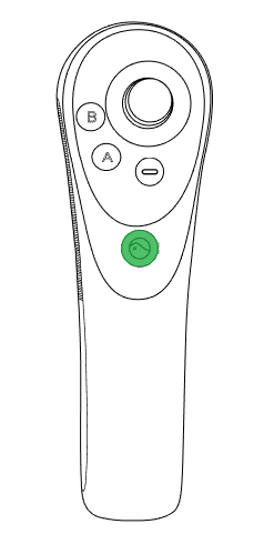
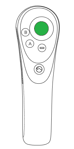
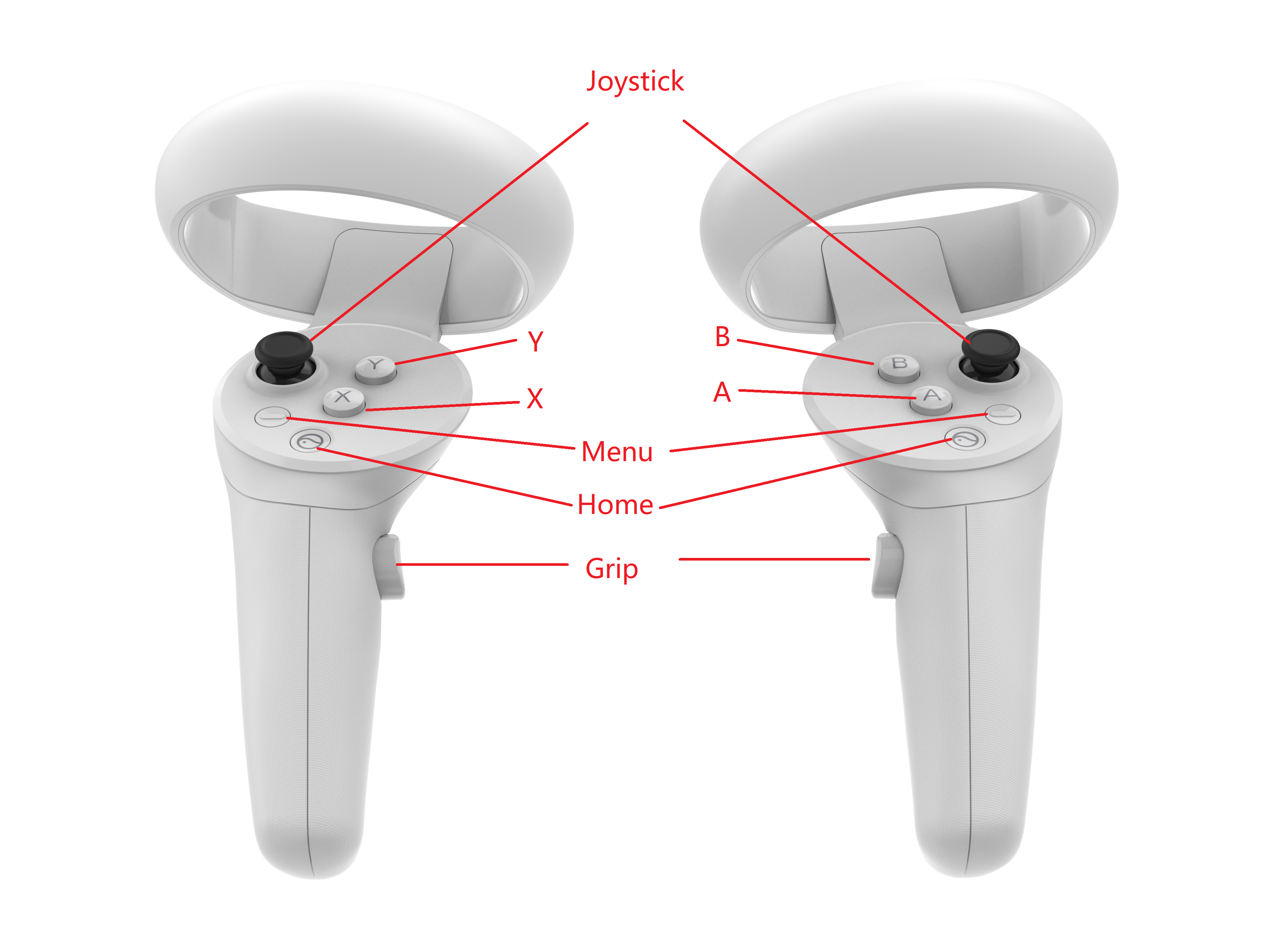
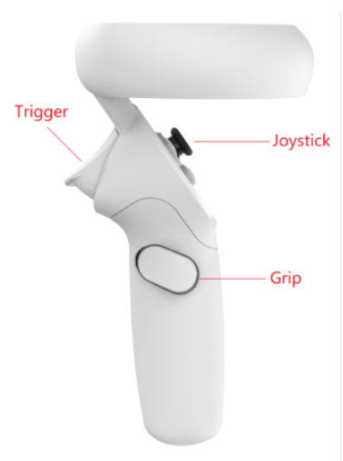
Pico Neo 3 uses a different design from Neo 2 that Neo 3 controller bends 34 degree comparing to horizontal plane when user holds it. See figure below for details.
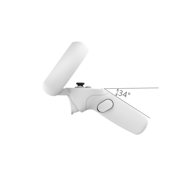
Fig 5.18 Pico controller angle diagram
Latest Pico SDK adds adjustment to the angle of controller model to allow application designed for Neo 3 can work well on Neo 2. To use latest SDK on Neo 2, it’s suggested to adjust the controller angle and adjust the controller 34 degrees on Pitch -axis.