8 Advanced features
This chapter describes several advanced features for some of the developer’s specific needs and optimizations.
8.1 Open Screen Fade of the Scenes
The SDK provides Open Screen Fade of the Scenes to be turned on through options as follows
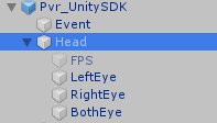
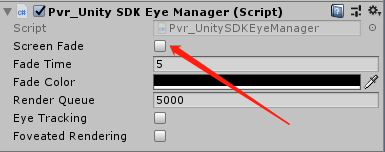
Figure 8.1 Opening of Screen Fade
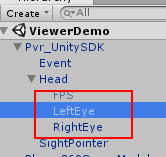
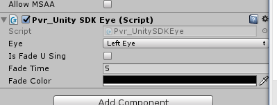
Figure 8.2 Fade Time and Fade Color after Opening the Scenes
8.2 Configure the size of EyeBuffer
The SDK provides the function of configuring the size of the Eyebuffer, which is opened by unchecking the “Use Default RenderTexture” option as follows
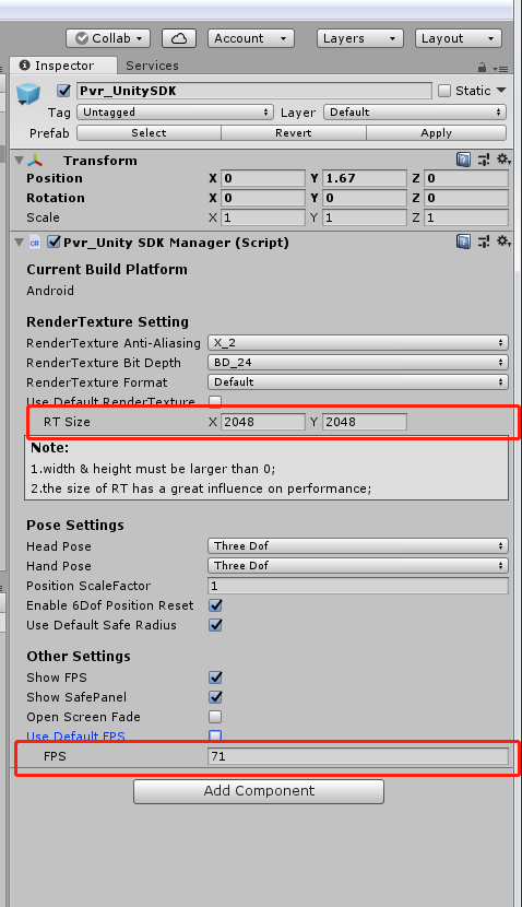
Figure 8.3 Configuration size of Eyebuffer
Tips:
Developers are advised to use the Use Default RenderTexture to use custom RT sizes only for special needs. For this option developers must understand the following two points:
- If the RT setting is too small, it will improve performance and reduce latency, but it will also result in lower resolution.
- If the RT setting is too large, it will reduce performance and increase latency, so it is not recommended that the RT setting exceed the hardware recommended texture size.
8.3 Custom Application Launch Animation
The SDK provides the function of customizing the application to launch animation. Click the menu bar Pvr_UnitySDK/ Splash Screen to open the Splash Screen editing interface, as shown in the figure:
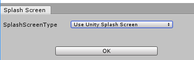
Figure 8.4 Splash Screen option
SplashScreenType contains three types of values: UseUnitySplashScreen, UsePicoSplashScreen, UseDynamicSplashScreen. Each type corresponds to a different application startup animation, and the following describes the configuration methods of the three startup animations.
8.3.1 Launch animation with the Unity app
SplashScreenType selects UseUnitySplashScreen, then click ok, the log message prompts Congratulations when the configuration is complete. At this point, the application startup animation uses the startup animation set in Unity PlayerSetting->Splash Image.
Note: This solution is not applicable to Neo3.
8.3.2 Launch animation with the default app provided by the Pico SDK
SplashScreenType selects UsePicoSplashScreen, then click ok, the log message prompts Congratulations when the configuration is complete. The application startup animation is now using the default startup animation provided by the Pico SDK.
8.3.3 Starting an animation with a custom app
SplashScreenType selects UseDynamicSplashScreen, the Splash Screen interface is as follows:
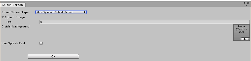
Figure 8.5 Splash Screen interface
SplashImage: An array of frame animation files that plays when the application starts. The order of the frame animation files in the array should correspond to the order of playback. Image pixel size should be less than 1080x720.
Inside_background: The background image of the application launch animation. Image pixel size should be less than 1080x720.
Use Splash Text: Startup copy when the app starts, check to enable it. After checking, the sub-items appear as shown below:
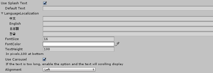
Figure 8.6 Use Splash Text option
Default Text: The default startup copy, if the system language of the device does not belong to any of the LanguageLocalization, the default startup copy is displayed.
LanguageLocalization: Fill in the corresponding startup copy content for different languages. When the application starts, it will select which startup copy to display according to the system language of the device. If the current system language is not included in LanguageLocalization, the Default Text default startup copy content will be displayed.
FontSize: Starts the copy text size.
FontColor: Starts the copy text color.
TextHeight: The distance from the start of the copy text to the bottom of the screen, in pixels.
Use Carousel: After the marquee, check the marquee function, if the text of the startup copy is too long, it will scroll.
Alignment: Starts the alignment of the copy text.
After all configuration items are configured, click the OK button to save the configuration. The Log message prompts Congratulations to be saved later.
Note: This solution is not applicable to Neo3.
8.4 Eye Tracking
Pico Neo 2 Eye supports eye tracking feature. Eye Tracking can track the eye gaze position, optimize rendering performance with Foveated Rendering.You can open Eye Tracking in the Pvr_UnitySDK under Head:
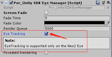
Figure 8.7 Eye Tracking
8.5 Foveated Rendering
Foveated rendering can optimize the rendering of VR scenes by providing full resolution (lossless) for the center of the field of view and reducing the resolution of peripheral views (outside the focus area of eyes).
Fixed foveation rendering (FFR) means the focus of the field of view is fixed in the center of viewport, and the definition will gradually decrease from the center to peripherals. Figure 8.10 shows how to enable and configure Foveated Rendering.
Dynamic foveated rendering (DFR) refers to that the focus of the field of view follows movement of eyesight. This feature only applies to Pico Neo2 Eye (supporting EyeTracking) and the configuration is as shown in Figure 8.6. Foveated rendering options can be found under Head object of Pvr_UnitySDK, just as illustrated in the following figure:
When checking “Foveated Rendering”, a sub option will appear. Choose an option of a certain level and then foveated rendering is enabled. There is no need for any extra code.
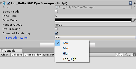
Figure 8.8 Foveated Rendering
Foveation Level: Available in Low, Med, High and Top High pre-defined levels. Usually it is suggested that developers choose the pre-defined level while not adjust the rendering details with self-defined parameters (unless developers bear a deep understanding of foveated rendering).
Apart from panel settings, Chapter 7.8 can help get/set the level of foveated rendering by calling foveated rendering related API and apply/self-define parameters of it.
Foveated rendering demonstration:
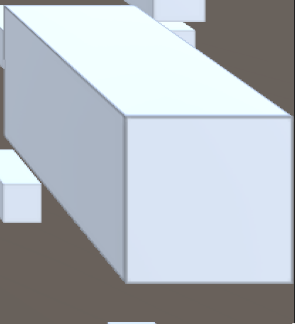
This demonstration is a screenshot of the bottom right at Low Level with 10 times zoom-in, and the image is a little blurred.
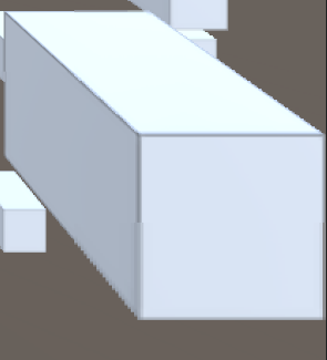
This demonstration is a screenshot of the bottom right at Med Level with 10 times zoom-in, and the image is more blurred.
This demonstration is a screenshot of the bottom right at High Level with 10 times zoom-in, and the image is much more blurred.
8.6 VR Compositor Layers
In SDK rendering pipeline, contents in the scene is rendered by LeftEye/RightEye cameras thenrendered to the “Eye Buffer”, after that “Eye Buffer” will be sampled by the ATW thread and finally rendered onto the VR screen.
The Compositor Layers (also known as “transmission layer”) provides a rendering method that is different from “rendering scene content directly into the eye buffer”: this method does not need to render the content to the “Eye Buffer”, but directly “transparently” the content to ATW thread for sampling and synthesis processing, thus avoiding a texture sampling process (rendering the content onto the “eye buffer”), which significantly improves the sharpness of the texture and video.
VR Compositor Layers is more useful when rendering messages, text, videos which are used as “Focus of the Scene”. Meanwhile it can also be used for simple scenes and backgrounds. Currently Compositor Layers supports up to 15 layers (more than 15 layers will not be displayed). And in each scene there can be 1 Equirect Layer and 1 Cylinder Layer at most. Considering drawback to the performance, we recommend limit number of layers to 4 for each scene.
Note that using Overlay should observe that nearby objects occlude distant ones, otherwise it may cause discomfort or slight shaking.
It is easy to use “VR Compositor Layers”. Just create an empty GameObject in Hierarchy view of Unity Editor and then drag the Pvr_UnitySDKEyeOverlay.cs script (path: PicoMobileSDK/Pvr_UnitySDK/Render/) into the GameObject created.
VR Compositor Layer property settings related to functions are as following:
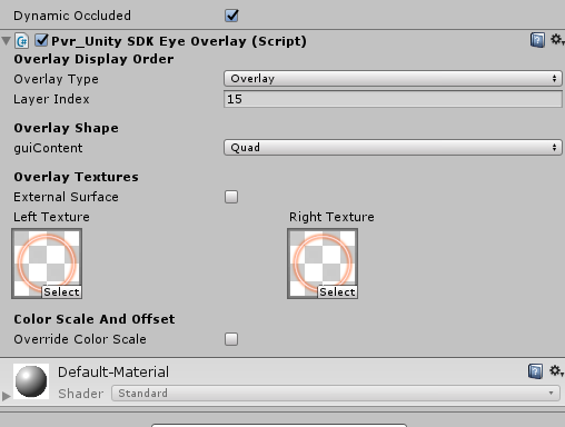
Figure 8.9 Settings
Detailed descriptions:
Overlay Type: set overlay type, default option is Overlay
Overlay: Texture will be displayed in front of “Eye Buffer”
Underlay: Texture will be displayer behind “Eye Buffer”
- Note: Underlay relies on alpha channel of render target, when all objects are drawn behind the “Eye Buffer”, developers will need to hollow out an area to display the Underlay texture, A ready shader UnderlayHole.shader (PicoMobileSDKPvr_UnitySDKResourcesMaterials) can be used. Or developers can choose to write their own shaders.
Layer Index: set reference value used for composite sequence (lower value means layer will be earlier to be composited)
- [Camera](Overlay)2/1/0[EyeBuffer]0/1/2(Underlay)
Overlay Shape: set overlay shape, default is Quad
Quad: Quadrate texture, normally used for Text or Messages in Scene
Cylinder: Curved cylinder texture, normally used for curved UI
Note 1: Centre of Transform component will be the centre of the cylinder, Transform.scale will be used for size of cylinder, [size.z] is radius of cylinder, [size, y] is height of cylinder, [scale.z] is arc length of cylinder
Note 2: When using Cylinder texture, camera needs to be placed inside inscribed sphere of the cylinder. Overlay won’t be displayed if camera is too close to the inscribed sphere surface.
- Equirect: Sphere texture, normally used for 360/180 video players (not available for Underlay currently)
External Surfaces: Checking this option indicates the layer will obtain texture from Android Surface externally. (e.g. texture of Android Player)
- Note: When enabled, an Android Surface will be initialized and managed by SDK, meanwhile rendering it directly onto Compositor Layer (We suggest enable External Surface to gain shaper video images, i.e. using Android player plugin to send video texture to Compositor Layer bypassing Unity)
Texture: Assign textures for left and right eye
- Left Texture: Texture to be displayed on left eye.
- Right Texture: Texture to be displayed on right eye.
Override Color Scale: Set the color scale and color offset of the layer
- Color Scale: the zoom scale of the color value of the layer
- Color Offset: the offset of the color value of the layer
8.6.1 Overlay & Underlay examples
In order to facilitate developers to quickly experience the 2D texture pass-through function, the SDK provides a 2DOverlay and a 2DUnderlay example, developers can directly package and install on the device to experience the effect (Note:Editor can not experience this function).
If the developer applies the feature to their project, follow these steps:
- Step 1: Open Unity to create an empty scene, find Pvr_UnitySDK.prefab in the
PicoMobileSDK/Pvr_UnitySDK/Prefabs/ folder and drag it into the empty scene, and delete the Main Camera object.
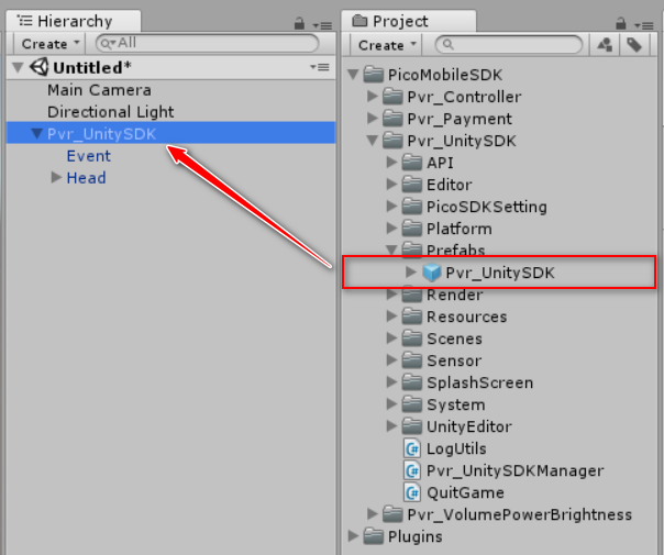
Figure 8.10 Drag into prefab
- Step 2: Create a Quad in the scene, name it OverlayTransform, then adjust the position of the Quad so that it is in the visible position of the Camera. After determining the display position, uncheck the Mesh Render and Mesh Collider components on the Inspector view panel.
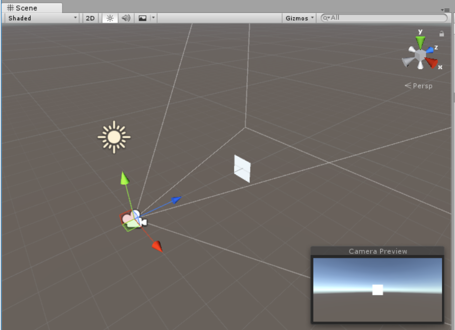
Figure 8.11 Create a Quad
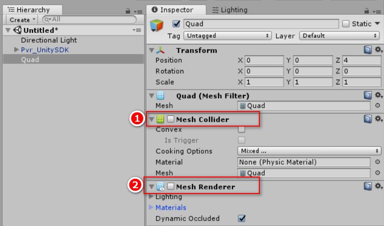
Figure 8.12 Cancel Mesh components
Tips:The Transmit Layer will use the Quad’s Transform information: position, rotation, scale.
- Step 3: Bind the Pvr_UnitySDKEyeOverlay.cs script to the Quad created in the previous step and adjust its property parameters on the inspector.

Figure 8.13 Bind script
- Overlay Type: Set overlay layer type as Overlay
- Layer Index: Set reference the rendering priority (Smaller value means higher priority for rendering);
- Overlay Shape: Select the overlay shape as Quad;
- Textures: Specify the 2D texture to be transparently transmitted (Tips: the left and right eyes specify the same texture, otherwise it will cause the left and right eye content to be different, causing dizziness);
- Color Scale and Offset: Adjust the parameters of chromatic aberration and color shift in the pass-through layer.
Tips: Developers who need to dynamically modify passthrough 2D textures can call the SetTexture (Texture Texture) interface in the Pvr_UnitySDKEyeOverlay. cs script.
- Step 4: The last step, package and install to the device to experience the effect.
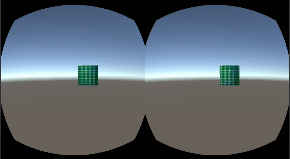
Figure 8.14 running result
8.6.2 360 panorama texture
Usually we need three steps to achieve “360 panoramic view”:
- Create a sphere model in the scene;
- Create a “360 Panorama Texture” material and assign it to the sphere model, then modify the shader to remove the front rendering (Cull Front);
- Place the Camera in the center of the sphere;
The “transmission layer” function requires only two step:
- Create an empty object in the scene and bind the Pvr_UnitySDKEyeOverlay.cs script;
- Set the Overlay shape as Equirect type and specify a “360 Panorama Texture”
In order to facilitate the developer to quickly familiarize the 360 panoramic texture transparent transmission function, the SDK provides a 360Overlay example, developers can directly package and install on the device to experience the effect (Note:Editor can not experience this function).
If the developer applies the feature to their project, follow these steps:
- Step 1: The steps are the same as the Overlay & Underlay examples;
- Step 2: Create an empty object in the scene, name it 360OverlayTransform, and bind Pvr_UnitySDKEyeOverlay.cs script;
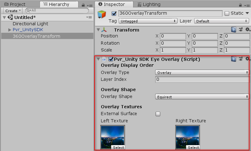
Figure 8.15 Create an empty object
- Step 3: Set property parameters on the script inspector;
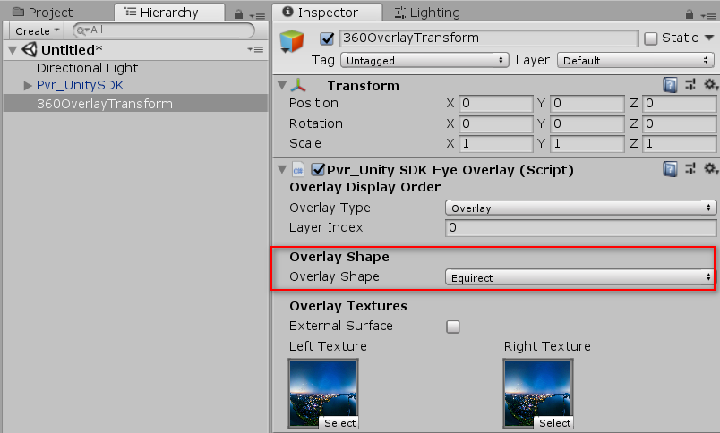
Figure 8.16 Set property parameters
- Overlay Type: Set overlay layer type as Overlay
- Layer Index: Set reference the rendering priority (Smaller value means higher priority for rendering)
- Overlay Shape: Set overlay shape as Equirect;
- Textures: Specify the same 360 panorama texture for the left and right eyes;
Tips:For Equirect type, we recommend disable Pvr_UnitySDKEye.cs script component of LeftEye and RightEye Camera to reduce rendering resources.
- Step 4: The last step, package and install on the device to experience the effect
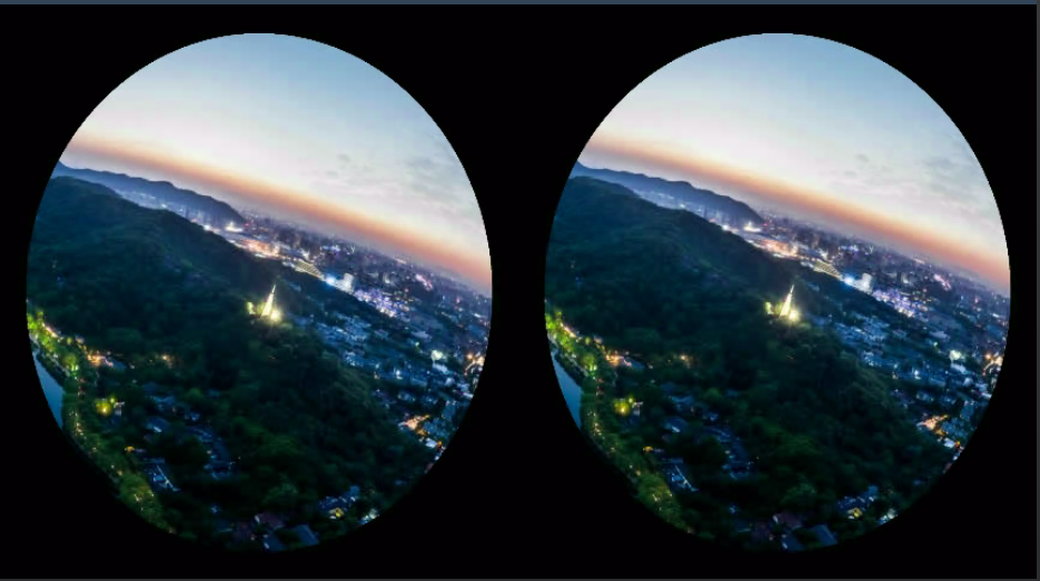
Figure 8.17 running result
8.6.3 Head-Locked & World-Locked Mode
By default, the “transmission layer” is World-Locked mode. If you want to implement Head-Locked mode, you only need to create an empty Transform under the Head node and bind the Pvr_UnitySDKEyeOverlay.cs script.
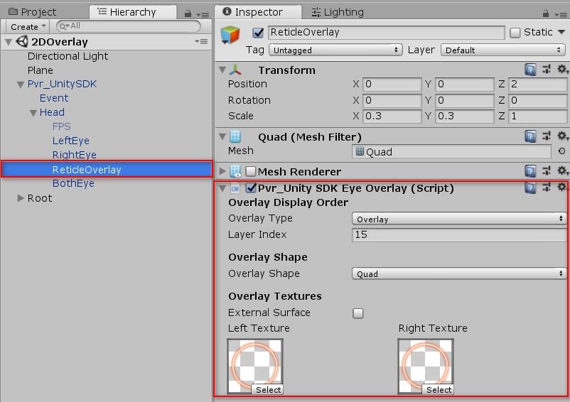
Figure 8.18 Head-Locked Mode
8.7 Monocular camera
Binocular camera: Provides a separate image for each eye from different angles, and the object will be closer to real life.
Monocular camera: Use a single image to render to both eyes, which effectively reduces rendering.
The way to enable a monocular camera is as follows: Check Use Monoscopic to enable the monocular camera, otherwise use a binocular camera.
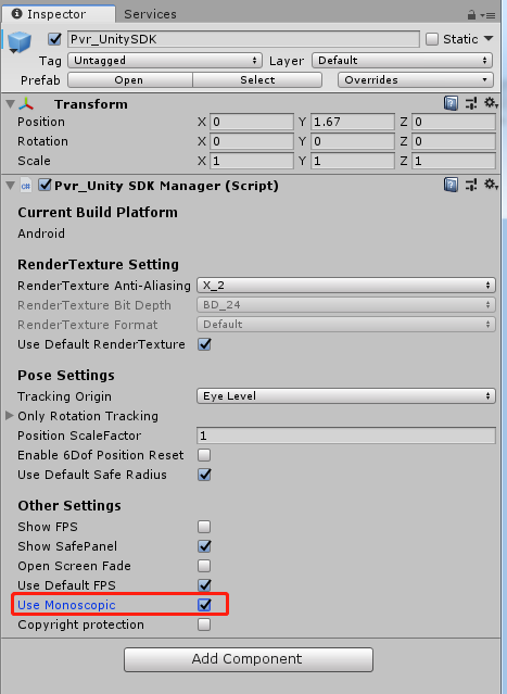
Figure 8.19 monocular camera
8.8 User entitlement check
Developers are allowed to use this function during development and debugging phases as well as final release to the Pico Store.
Entry: go to Menu/Pvr_UnitySDK/ Platform Settings, and enable “User Entitlement Check”.
User entitlement check does not require connection to the Internet. The SDK provides a return code that is the check result, but no extra processing is done. Developers need to deal with the failed situations. For example, if you receive “not successful”, show the user the failure reason and exit the app, or enter Demo mode, and prompt the user to go to Pico Store to buy the full version.
8.8.1 Entitlement check simulation during development and debugging phases
In the development stage, developers can simulate the user entitlement check process by filling in the development device SN code in the configuration interface, and the processing logic after the check is failed to test the effect.
In the menu, click Pvr_UnitySDK then Platform Settings to open up Platform Settings menu as shown in the picture below:
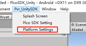
Figure 8.20 Platform Settings Option
Entitlement Check Simulation is disabled by default. After checking this option, developers can type in allowed device number and corresponding SN code. It provides entitlement check validation function, which is used for simulating if user entitlement check is working correctly.
Methods to get SN code of the device:
1.Enter Settings – About – Serial Number
2.Use adb command “adb devices” to get device SN code,
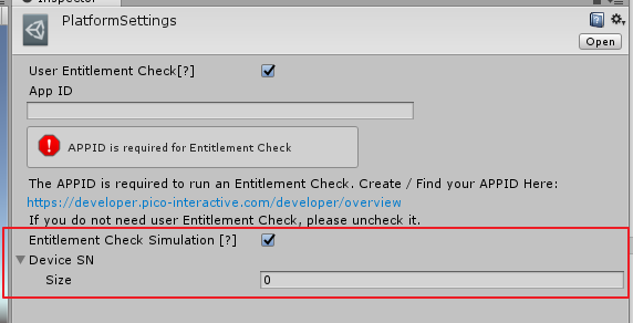
Figure 8.21 Platform Settings Inspector
Related API are listed in Chapter 7.9
8.8.2 User entitlement check after official release
The figure below shows that after User Entitlement Check is checked, inputting the correct App ID can enable this function. The App ID is the unique ID assigned to an app by the Pico Developer Platform. It can be applied and viewed at https://developer.pico-interactive.com/developer/overview.
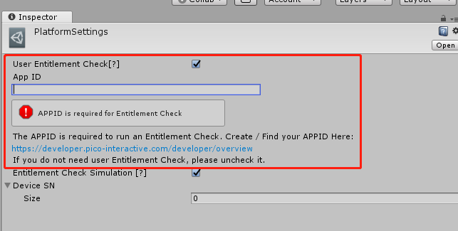
Figure 8.22 Platform Settings
The Pvr_UnitySDKManager.EntitlementCheckResultEvent event can be monitored with code and the corresponding return values can be dealt with. For detailed information, please refer to the sample scenario provided by SDK at AssetsPicoMobileSDKPvr_UnitySDKScenesExamplesUserEntitlementCheck.unity.
The list of return values are as follows.
| Return value | Implication |
|---|---|
| 0 | Success. |
| -2 | Service does not exist. |
| -3 | Service binding failed. |
| -4 | Catching exception code. |
| -5 | Timeout. |
| 10 | The package name is missing. |
| 11 | The APPID is missing. |
| 13 | The package name and APPID do not match. |
| 20 | The user has not logged in. |
| 21 | The user has not purchased. |
| 31 | The application was not found. |
| 32 | The purchasing SN number does not match with the device SN number. |
Notes: Development devices with SN code filled in the entitlement check simulation will pass the user entitlement check by default after the app is uploaded to the Pico Store, and no formal user entitlement check will be carried out. If developers need to carry out formal user entitlement check on the development device after the app is on the Pico Store, please close the “Entitlement Check Simulation” when compiling the formal version.
8.9 Tracking Origin
SDK allows setting the Tracking Origin. The default value is EyeLevel. When set to FloorLevel, tracking origin will be calculated by the height above the ground detected by headset. (Only applicable on supported devices)
EyeLevel is recommended for sitting usage while FloorLevel is better for standing usage.
StageLevel is based on FloorLevel and calibration does not reset the positive direction of the scene.
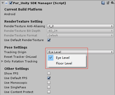
Figure 8.23 Tracking Origin Options
8.10 SinglePass
SinglePass is based on native Unity SinglePass feature. It uses one camera to fulfill stereo rendering, reducing half of Draw Call and Occlusion Culling. Using this feature can increase frame rate dramatically in complex scenes. But SinglePass don’t support post processing.
Check “Use SinglePass” to enable SinglePass mode. Uncheck “Use SinglePass” to disable SinglePass mode.
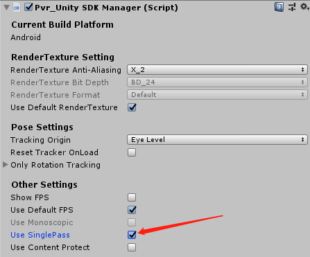
Figure 8.24 Enable SinglePass
8.11 Anti-aliasing multiple setting
The SDK provides the recommended anti-aliasing multiple setting function, which is turned on by selecting the Use Recommended MSAA option. The currently recommended MSAA value is 4, and the method to open it is shown in the figure 8.25. Uncheck it to customize it yourself.
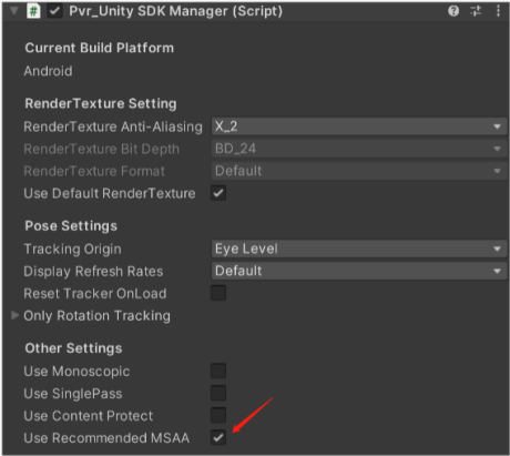
Figure 8.25 Use Recommended MSAA
8.12 Quick compilation tool
The tool leverages gradle cache to speed up the build process. It only updates the increment of compilation during the compilation process by using gradle cache, thus reducing the time for compilation and deployment by 10% to 50% compared to that of the Unity’s compilation file, and the final.apk file is exactly the same as the Unity’s compilation file. However, to release the final.apk, you must use Unity’s compilation function.
To use this function, please follow these steps:
1.Open Build Settings and select scenes that you want to package
2.Click Pvr_UnitySDK->Build Tool->Build And Run in the menu bar
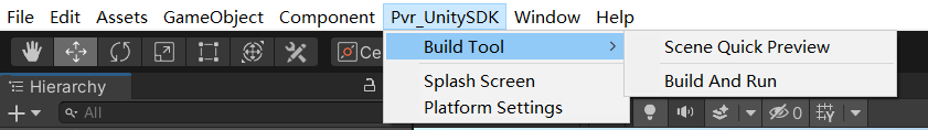
Figure 8.26 Quick compilation
Specific SDK adaptation methods for various hardware products of Pico VR will be given in detail in the following chapters.
8.13 Scene Quick View Tool
This tool decompose project into multiple asset bundles and upload to Pico devices. When developer made changes to the project, using this tool will update only essential changes to Pico devices when building new version.
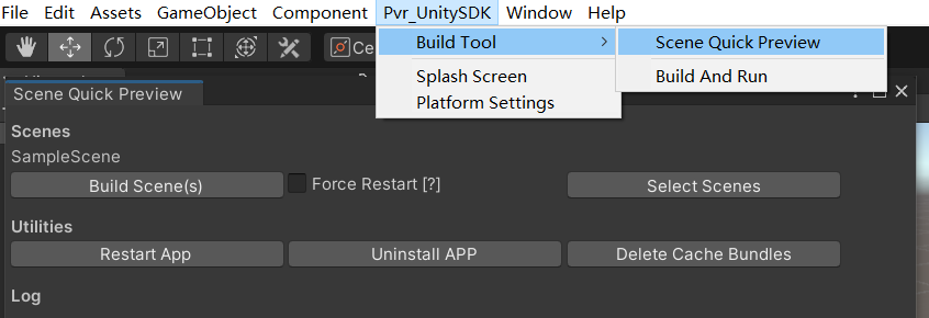
Figure 8.27 Scene Quick Preview
To use Scene Quick Preview, please follow the steps below:
From Menu Bar select PXR_SDK -> Build Tool -> Scene Quick View to open Quick View Panel.
Click “Select Scenes” button and choose the scenes for Quick View Tool to build.
Click “Build Scenes(s)” button and start compiling.
Additionally, you may also use following:
“Force Restart[?]”: When this option is enabled, the application restarts on each re-compiling.
“Restart APP”: Restart the application.
“Uninstall APP”: Uninstall the application.
“Delete Cache Bundles”: Delete cache files generated during compilation